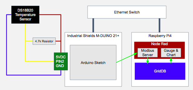
In this demonstration, we show how you to build a low cost Industrial Internet of Things (IIoT) solution using GridDB on a Raspberry Pi 4 with a Node-Red flow that uses Modbus to read temperature sensor data from an Industrial Shields M-DUINO 21+ Arduino PLC.
Table of Contents
- Raspberry Pi Setup
- Raspberry Pi OS
- GridDB on Raspberry Pi
- NodeJS, GridDB Node client
- Install Node Red
- PLC Setup
- Hardware Setup
- Arduino Setup
- Create the Node Red Flows
Raspberry Pi Setup
First, we’re going to start by getting our Raspberry PI up and running. We need to install Ubuntu and build and install the GridDB Server, NodeJS, GridDB NodeJS Client along with Node Red and the Nodes we’ll be using.
Raspberry Pi OS
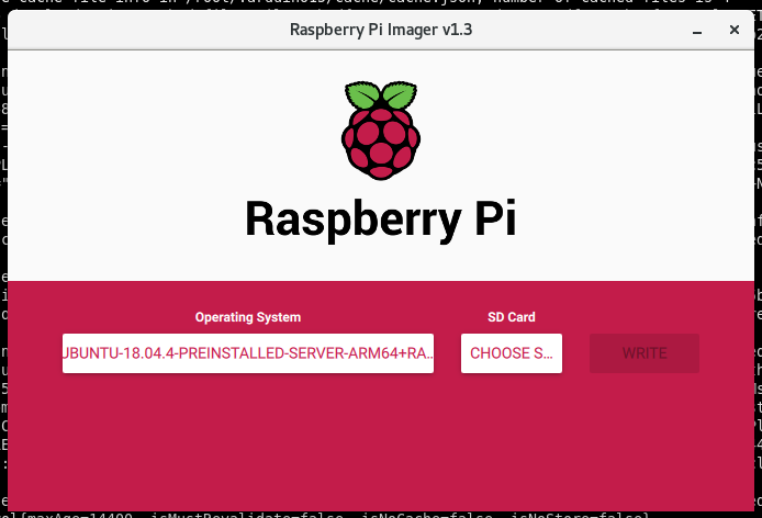
GridDB needs to run on a 64-bit OS, so we’ll use Pi Imager to write a 64-bit Ubuntu 18.04 server image to our micro SD card.
GridDB on Raspberry Pi
Now that you can log into the Pi, we can follow this blog post on how to compile and run GridDB on an ARM64-based Raspberry Pi.
NodeJS, NodeJS GridDB Client
To build the Node.js client required for Node-RED, we need to install Node.js, its development headers, and node native abstractions for Node.js.
# sudo apt-get install nodejs nodejs-dev node-nan
Now we need to build dependencies for the Node.js GridDB client, PCRE and SWIG.
$ export LD_LIBRARY_PATH=/usr/local/lib
$ wget https://sourceforge.net/projects/pcre/files/pcre/8.39/pcre-8.39.tar.gz
$ tar xvfz pcre-8.39.tar.gz
$ cd pcre-8.39
$ ./configure
$ make
$ make install

$ wget https://prdownloads.sourceforge.net/swig/swig-3.0.12.tar.gz
$ tar xvfz swig-3.0.12.tar.gz
$ cd swig-3.0.12
$ ./configure
$ make
$ make install
With the prerequisites built, we can clone and build the Node.js GridDB client.
$ git clone https://github.com/griddb/nodejs_client.git
$ cd nodejs_client && make
Install Node Red
Now we can install Node Red and the Nodes we’re going to use:
# npm install node-red
# mkdir ~/.node-red
# cd ~/.node-red
# npm install node-red-contrib-modbus@3.6.1 node-red-dashboard
The GridDB Node Red Node isn’t available from npm yet,
# cd ~
# git clone https://github.com/griddbnet/node-red-contrib-griddb.git
# cd ~/.node-red
# npm install ~/node-red-contrib-griddb
Now we add the GridDB Client to our NODE_PATH and start node red.
# export NODE_PATH=:/home/ubuntu/nodejs_client
# ~/node_modules/node-red/bin/node-red-pi
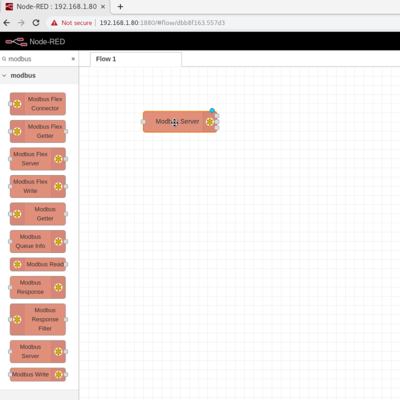
Now, you can visit the Node-Red web page at http://your_pi_ip:1880/. We’re going to add the Modbus server so the mduino application will start properly.
PLC Setup
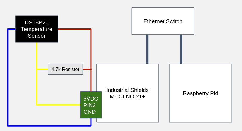
Hardware Setup
For the hardware setup, we’re going to mount the hardware to a DIN rail, wire the temperature sensor, setup the Arduino IDE, and deploy our Arduino sketch to the PLC.
We mounted the Raspberry Pi4 to a DINRplate for a clean installation on a DIN rail and are using a generic terminal block from Amazon. Having everything mounted on the DIN rail will keep it neat and tidy, something very beneficial if you have 100s of temperature sensors.
The ground wire of the temperature sensor is connected to the M-DUINO’s ground pin. The 5 volt wire is also connected to the M-DUINO’s +5 VDC pin. The sensor wire is connected to Pin2 and a 4.7k Ohm resistor is placed between the +5 VDC bus and the sensor bus. Multiple DS18B20 sensors can be attached to the same M-DUINO pin if you have a large enough terminal block which is one advantage of using the DS18B20 over using an Analog sensor.
Arduino Setup
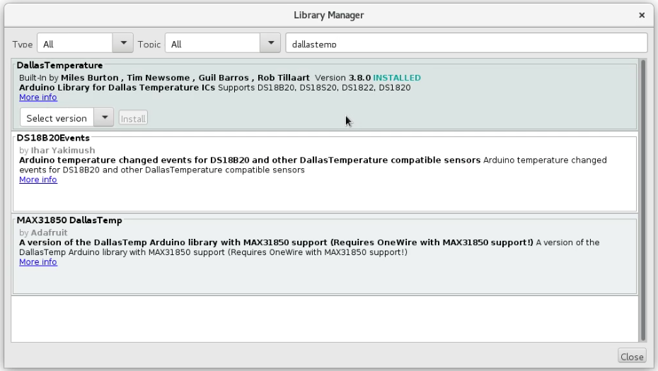
After installing and starting the Arduino IDE for your preferred OS (It can be on the Raspberry Pi but I prefer to connect it directly to my development workstation) install the Arduino Modbus and DallasTemperatrure libraries into the Arduino IDE.
For the Arduino setup, the required headers are included and our M-Duino’s mac and ip address are configured. We’re using PIN2 to receive the signal from our DS18B20 so we configure the OneWire library appropriately.
Then we configure the ModBus server address which will run on the Raspberry Pi. The actual startup routine simply starts ethernet and serial.
#include <SPI.h>
#include <Ethernet.h>
#include <ArduinoRS485.h>
#include <ArduinoModbus.h>
#include <OneWire.h>
#include <DallasTemperature.h>

byte mac[] = { 0xBE, 0xAD, 0xBE, 0xEF, 0xFE, 0xED };
byte ip[] = { 192, 168, 1, 100 };

#define ONE_WIRE_BUS 2
OneWire oneWire(ONE_WIRE_BUS);
DallasTemperature sensors(&oneWire);

EthernetClient etherClient;
ModbusTCPClient modbusTCPClient(etherClient);

IPAddress server(192, 168, 1, 80); // Modbus server
void setup() {

  Ethernet.begin(mac, ip);
  Serial.begin(9600);

}
The Arduino’s loop function runs every second, ensuring we have a Modbus server connection, collecting the temperature, multiplying it by 100 so it will fit in a 16-bit integer Modbus register, and sending sending it.
void loop() {

  if (!modbusTCPClient.connected()) {
    Serial.println("Attempting to connect to Modbus TCP server");

    if (!modbusTCPClient.begin(server, 10502)) {
      Serial.println("Modbus TCP Client failed to connect!");
    } else {
      Serial.println("Modbus TCP Client connected");
    }
  } else {

    sensors.requestTemperatures();
    float temp = sensors.getTempCByIndex(0);
    Serial.print("Temperature is: ");
    // convert the temperature to int and multiply by 100 to not loose precision
    unsigned int tempbin = (int)(temp*100);
    Serial.println(tempbin);

    if (!modbusTCPClient.holdingRegisterWrite(0, 0x00, tempbin)) {
      Serial.print("Failed to write register! ");
      Serial.println(modbusTCPClient.lastError());
    }

    delay(1000);
  }
}
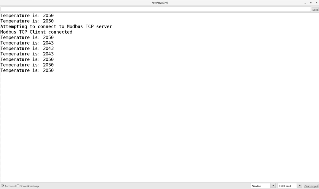
Now with our Arduino code complete we can compile, upload and verify it’s working.
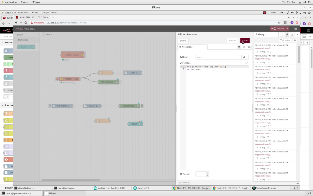
Create the Node Red Flows
We’ve already added a Modbus Server node to our flow, now we will create two more sets of connected nodes. The first set reads from Modbus, transforms the data into the structure expected by the GridDB-Put node and then inserts into GridDB.
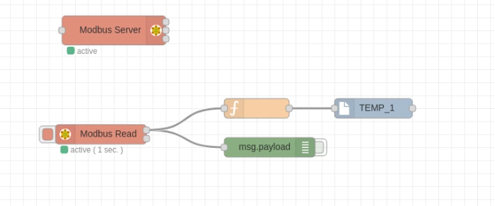
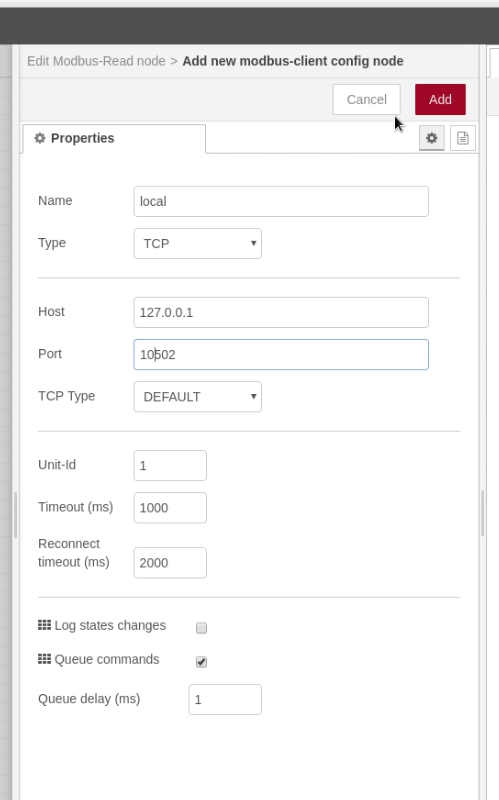
First, the Modbus Read Node needs to be configured to connect to the Modbus server.
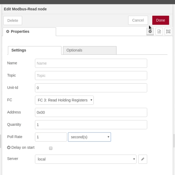
Then, it can be configured to read the registers we are writing the temperature value to.
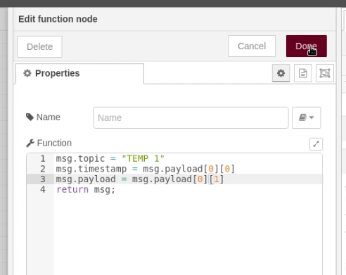
We transform the data so it is suitable for input to the GridDB-Put Node. The temperature is divided by 100 as it’s multiplied by 100 to not loose precision and converted to an integer to fit into the Modbus register.
![]()
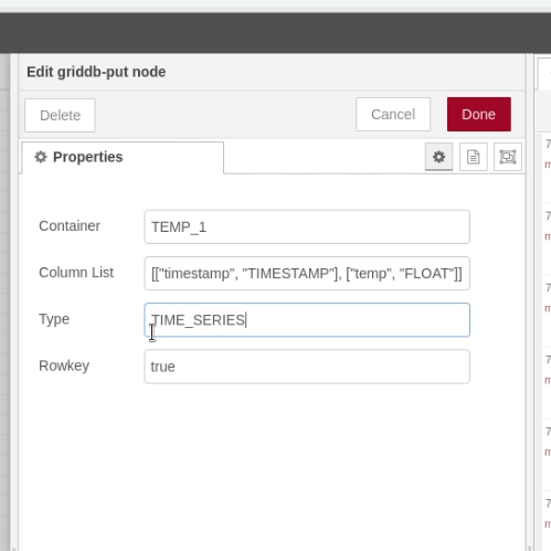
The GridDB Put Node is configured with the container to write its schema.
The second set of connected nodes reads from GridDB and display the values using Dashboard Nodes.
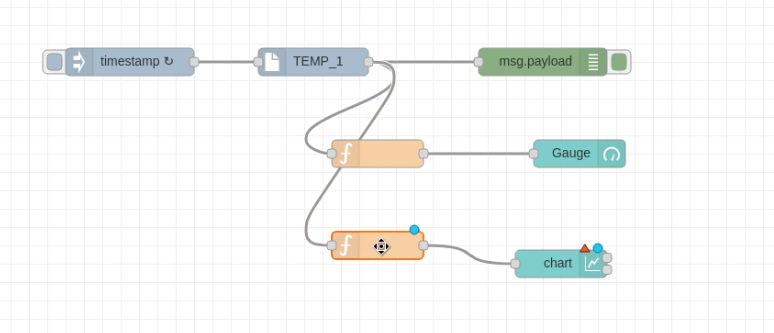
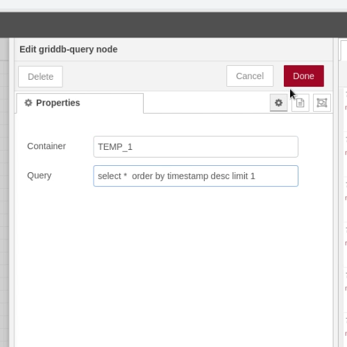
The latest data is fetched from the GridDB container being written to above:
The data output by the Query Node needs to be transformed to be usable by the Gauge Dashboard element. The Gauge Node itself needs no actual configuration.
Like above, the data needs to be transformed to be usable by the Chart. The Chart node itself needs no actual configuration.
Now with both sets of connected nodes deployed we open the Dashboard page and can see the simple visualizations from the data collected from our PLC: http://your_pi_ip:1880/ui/
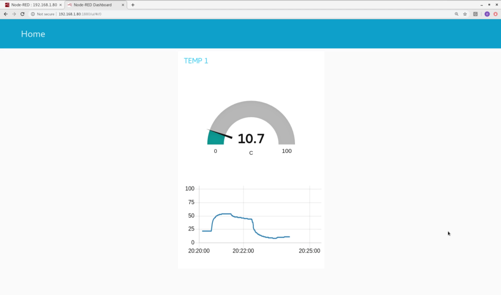
Your digital temperature sensor, Arduino PLC, Raspberry PI have now been connected together with Modbus, GridDB, and a Node-Red Flow to create a simple IIoT solution that can be easily expanded with more temperature sensors or other sensor types.
If you have any questions regarding this project or anything else related to GridDB, please feel free to ask on StackOverflow: https://stackoverflow.com/questions/ask?tags=griddb